Sensors and integrations
Contents
3. Sensors and integrations
3.1. CTD Sensors
On gliders, currently three types of CTD-sensors are in use (see Table 1). CT sensors can be unpumped (Sections 3.1.1.1; 3.1.2) or pumped (Section 3.1.1.2). Unpumped CT sensors have lower power consumption requirements as well as reduced susceptibility to blockages/failures because of the larger throughflow pipe (Section 6.2.4). There is also reduced background vibration and noise, which is advantageous when measuring microstructure (Fer et al., 2014). However, the disadvantage of the unpumped sensors is in the post processing correction for the effects of thermal-inertia because the flow rate through the inlet is not known and has to be estimated from the glider’s flight model (Section 8.1). Pumped CT sensors on the other hand, have a constant through-flow rate, allowing for a simpler correction of thermal-inertia. Nevertheless, both pumped and unpumped sensors require corrections for thermal-inertia (Section 8.1).
3.1.1. Sea-Bird
Conductivity, temperature and depth (CTD) sensors distributed by Sea-Bird electronics are currently the most widely used sensor on gliders.
3.1.1.1. Unpumped
The CT-Sail, a free-flushed (unpumped) CTD (SBE41), was the first science payload installed in the Seaglider (Janzen and Creed, 2011) and remains widely in use. The separate temperature and conductivity sensors are installed on the upper side of the glider pressure hull and integrated with the internal glider data acquisition and flight control system. On the CT-Sail the temperature sensor is positioned beneath and parallel to the conductivity sensor. The conductivity sensor itself is positioned within a metal housing with hole cut-outs to allow for flushing. The pressure sensor is located ~40 cm in front of the thermistor, requiring a slight spatial alignment with the sensors. Power consumption is 21 mW while profiling.
Sea-Bird provided CTD SBE41-sensor accuracy ratings: Conductivity: ± 0.0003 S m-1 over a range of 0 to 7 S m-1; Temperature: ± 0.002oC over a range of -5 - 45oC and Pressure: ± 2 dbar over a range of 0-2000 m.
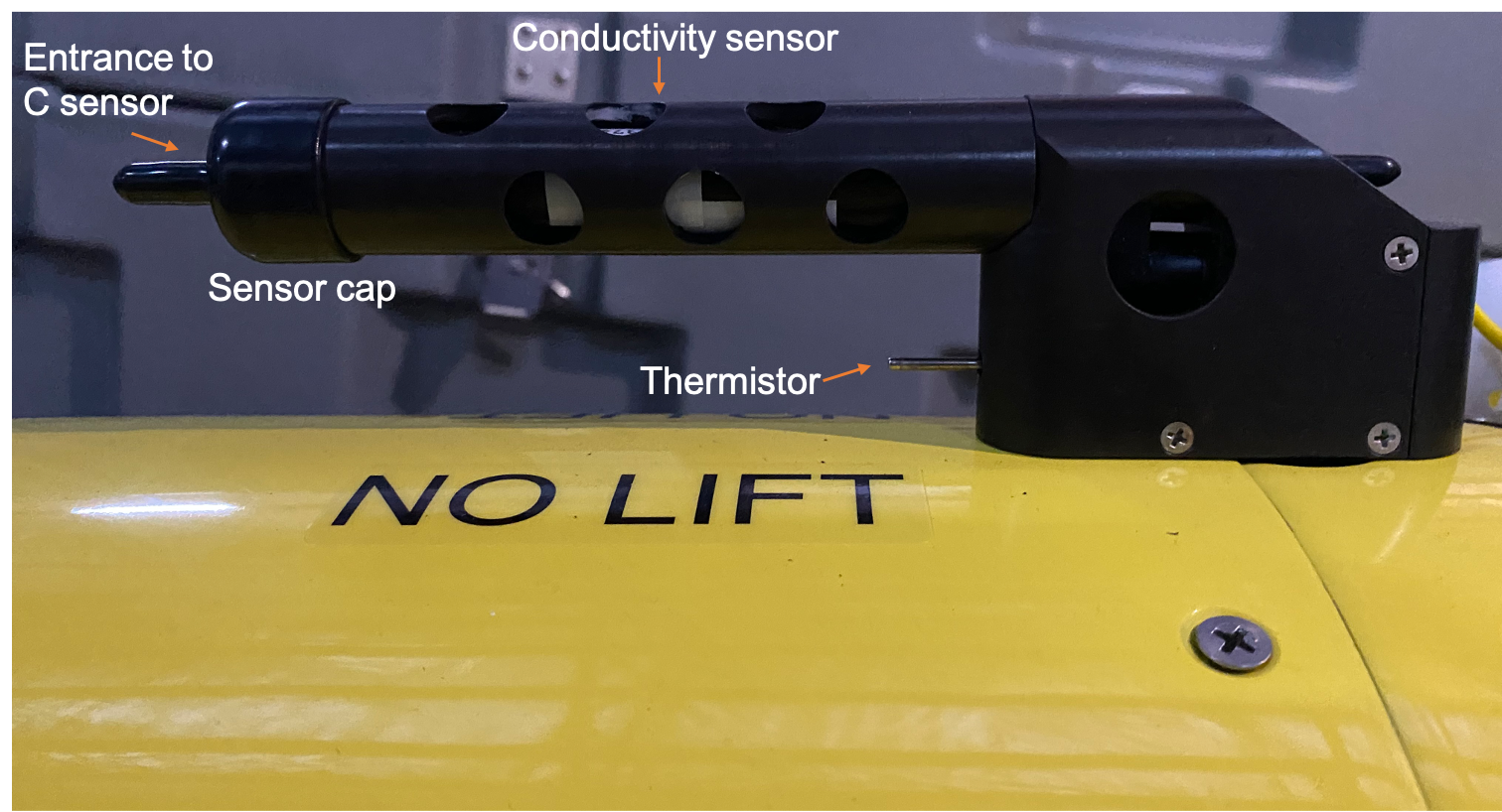
Fig. 3.1 CT-Sail with metal housing, thermistor located beneath the salinity sensor. (Figure credit: Isabelle Giddy)
3.1.1.2. Pumped
The Glider Payload CTD (GPCTD) is a modular, self-contained CTD with memory and an integrated pump. The GPCTD improves on the CT-Sail through simpler installation requirements as well as a pump which allows for constant flow through the conductivity sensor. The CT sensors are ducted and pumped on the GPCTD with the intake positioned to minimize measurement errors caused by the vehicle’s thermally contaminated boundary flow (Janzen and Creed, 2011). Power consumption is 175 mW when continuously recording at 1 Hz.
Sea-Bird provided GPCTD accuracy ratings are: Conductivity: ± 0.0003 S m-1 over a range of 0 to 9 S m-1; Temperature: ± 0.002oC over a range of -5 - 42oC and Pressure: ± 0.1% of full scale range, up to 2000 m.
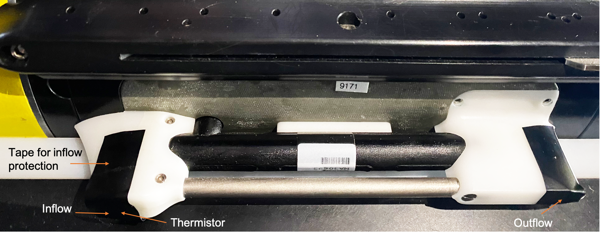
Fig. 3.2 Slocum Glider CTD (pumped). The thermistor is located within the inflow valve on the left (Image credit: Isabelle Giddy)
A variation of the GPCTD, the Slocum Glider CTD has been developed for installation on SLOCUM gliders. The sensor is installed on the side of the SLOCUM. The continuously pumped CTD consumes 240 mW sampling continuously at 0.5 Hz.
3.1.2. RBRlegato3
The RBRlegato3 is an integrated CTD and logger package designed specifically for gliders with a hydrodynamic profile. It is available in slow (1 s) and fast (0.1 s) response temperature options as well as normal (2 Hz) and fast (16 Hz) sampling speeds. The RBRlegato3, unlike the previously mentioned sensors, has an inductive cell rather than conductive, with significant implications for sensor calibration of salinity. Its advantages are a large unpumped flow cell, reducing occurrence of spikes due to bubbles and fouling. As such, it is very good for near-surface applications and slow glider speeds, as well as for glider missions involving instrumentation sensitive to vibration (e.g., shear probes) or noise (e.g., acoustic packages). The RBRlegato3 has low power consumption (45 mW) when sampling at 2 Hz. Its profile and low power have many benefits, but the inductive cell and relative youth of the sensor leave some open questions regarding long term accuracy. As a logger, the RBRlegato3 can also integrate other RBR sensors (such as the oxygen optode RBRcoda3 T.ODO) enabling fast 16 Hz sampling even if the glider platform does not have the capability onboard and reduces the number of sensor ports required to connect to the glider.
The RBRlegato3 has a manufacturer-provided accuracy of ±0.0003 S m-1 over a range of 0 to 9 S m-1 for Conductivity, ± 0.002oC (ITS-90) over a range of -5 to +35oC for Temperature, and ± 0.05% full scale for Pressure, up to 1000 m.
3.2. Sensor integrations with gliders
3.2.1. Mounting location
3.2.1.1. Seaglider
On Seagliders the Sea-Bird electronics supplied CT-Sail is mounted on the upper side of the glider pressure hull. Flow past the CT sensors relies solely on the movement of the glider. Sea-Bird no longer lists the CT-Sail, but it is manufactured on request by integrators. The Glider Payload CTD replaces the CT-Sail and was developed for easier integration and improved data output associated with the addition of a pump to control flow past the sensors. The GPCTD is installed between the pressure hull and the fairing in the aft-flooded payload bay.
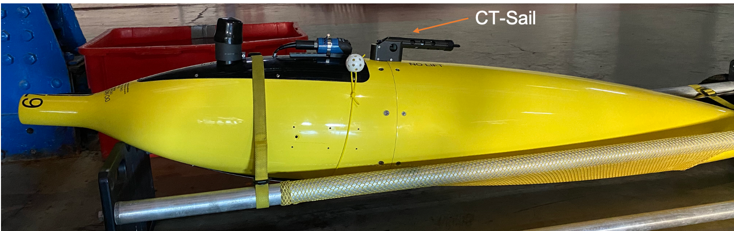
Fig. 3.3 Unpumped CT-Sail mounted above the pressure hull on a Seaglider. (Image credit: Isabelle Giddy)
3.2.1.2. Spray
Spray gliders use the pumped Sea-Bird 41CP, which is slightly different from the Glider Payload CTD. The differences are largely in the packaging and plumbing.
On Spray, the SBE 41CP is mounted on the dorsal side of the aft wet bay. Sampling is only during the ascending phase of each dive when the glider’s angle of attack provides clean flow to the intake.
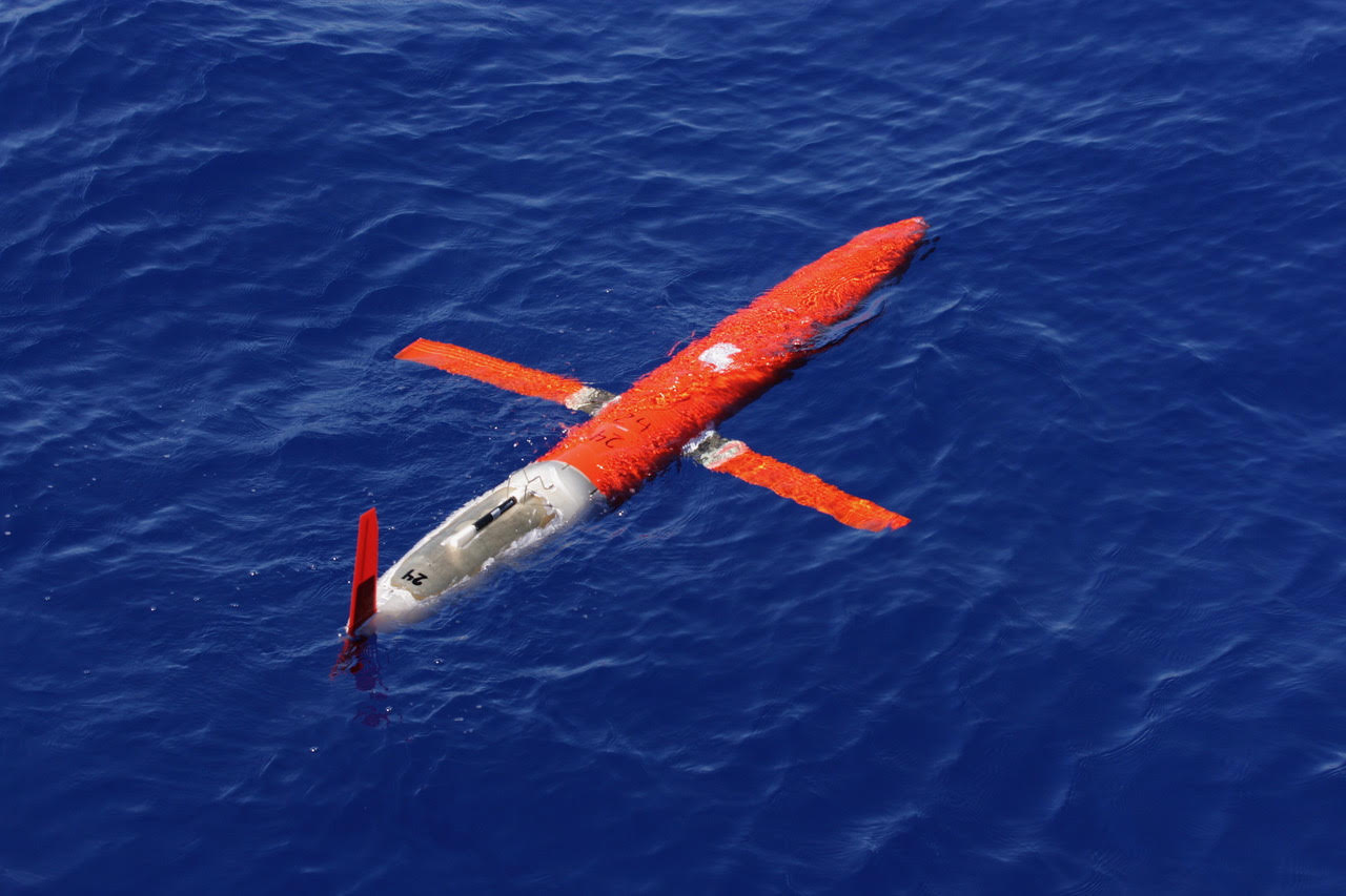
Fig. 3.4 Spray glider. The conductivity cell is the black cylinder on top of the white tail section; the thermistor is in the intake just forward of the conductivity cell. Two metal guards forward of the intake provide protection to the CTD. (Image credit: Robert E. Todd)
3.2.1.3. Slocum
On slocum gliders, an adaptation of the GPCTD, the Slocum Glider CTD, is installed beneath a wing on the lateral side of the glider.
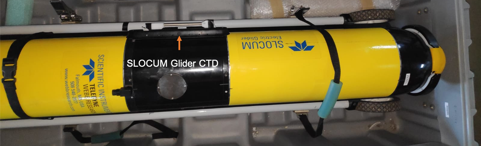
Fig. 3.5 Slocum Glider CTD installed on a Slocum G2 beneath the wing. (Image credit: Isabelle Giddy)
3.2.1.4. SeaExplorer
On SeaExplorer gliders, the CTDs are typically installed in the flooded nose cone area (Fig. 3.6, left), though the RBRlegato3 can also be configured to be installed through one of the top/side “puck” ports to leave the nose available for other sensors (e.g. acoustic payloads) as shown in Fig. 3.6, right.
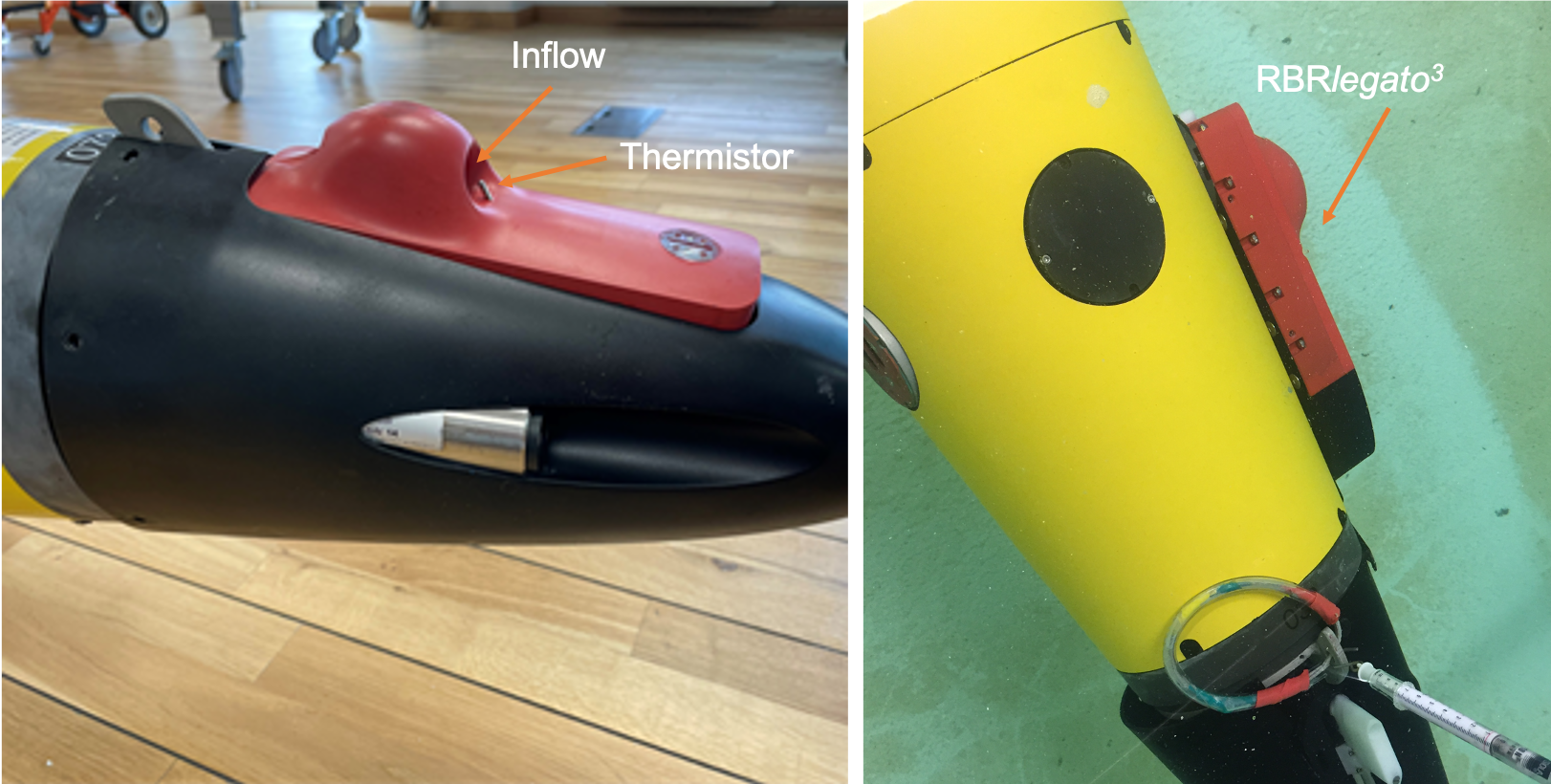
Fig. 3.6 RBRlegato3 CTD on SeaExplorer (Image credits: Bastien Queste (left) and Clark Richards (right))
In the case of the Sea-Bird GPCTD, the sensors are integrated on the wet payload part located on the front nose of the SeaExplorer glider, with the integrated pump providing a constant flow through the conductivity cell.
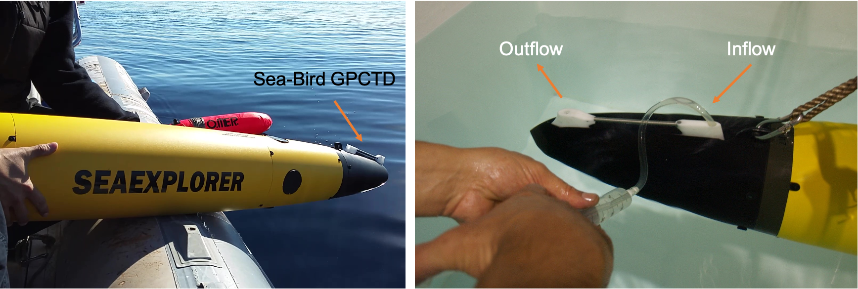
Fig. 3.7 Left: Sea-Bird GPCTD on SeaExplorer; Right: GPCTD on SeaExplorer during in lab preparation (Image credit: Evi Bourma)
3.2.1.5. Petrel Glider
The small-size RBRlegato3 CTD is embedded in the front fairing of the Petrel glider. The CT sensors are exposed outside the fairing to sense the ambient seawater. This integration design can minimize the impact of the CTD on the streamline of gliders.
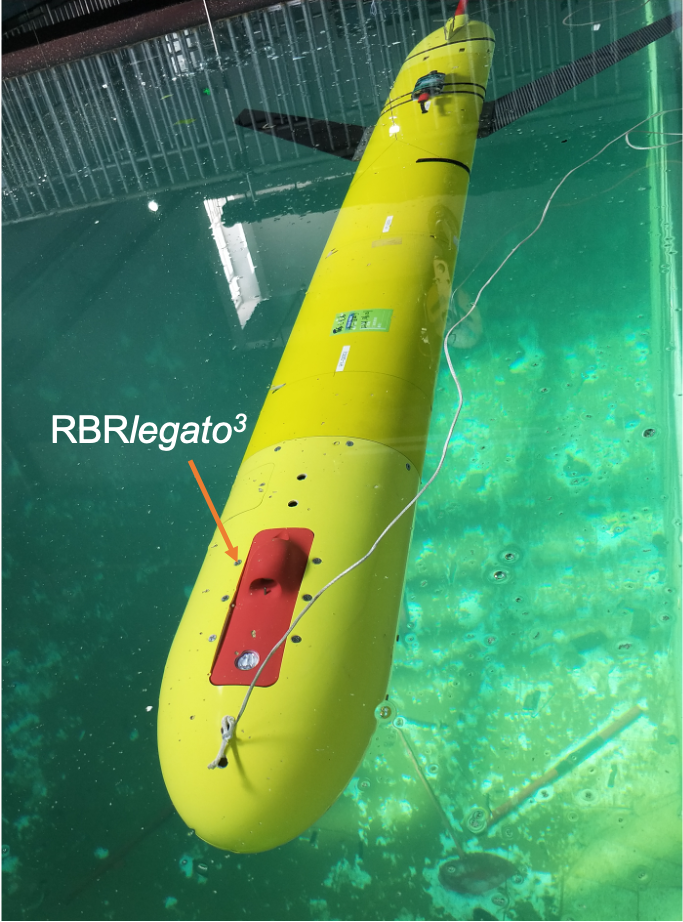
Fig. 3.8 RBRlegato3 Petrel Glider integrated an RBRlegato3 CTD in the front fairing. (Image credit: Joe Wang)
3.2.2. Sensor sampling rates
While each sensor has a range of sampling rates that can be set, the real limitation is set by the processing system associated with the platform.
Sensors integrated on Seagliders are limited to once every 5 seconds (0.2 Hz), unless the Seaglider is installed with a scicon board (discontinued).
SeaExplorers have a dedicated ARM processor and can handle up to 16Hz.
Older Slocums with a persistor typically sample once every 4 seconds (0.25 Hz). This can be changed to once every 2 seconds (0.5 Hz) when the science persistor has ‘free’ time, meaning when you do not have too many other sensors. Recent models (eg. G3) can handle faster sampling rates.
Sampling on Spray is 0.125 Hz (every 8 seconds).
3.2.3. Sensor storage
Sensors are stored dry with sensor caps on or tape to cover open valves, and protected from dust and freeze.