Required Metadata, Real Time Data Processing & Quality Control
Contents
6. Required Metadata, Real Time Data Processing & Quality Control
This chapter has to be co-developed with the OceanGliders Data Management Task Team, the Data Assembly Centers (DACs) and RTQC Best Practice group to ensure to build on their work.
6.1. Required Metadata and Real Time Data Processing
XXX
6.2. Real Time Quality Control (RTQC)
XXX
6.2.1. Global range check
XXX
6.2.2. Outlier and spike check
XXX
6.2.3. Stuck value test
XXX
6.2.4. Pump malfunction
While pumped conductivity cells are desirable as thermal-inertia is generally reduced, pumped conductivity cells are more prone to malfunction than unpumped cells. The two primary issues experienced by the pumped cells are 1) pump failure and 2) biofouling.
You could examine the pump failure in the following way: Doing a simple experiment in the lab by using a syringe with blue dye to evaluate the performance of the CTD pump (Fig. 6.1 ). In addition, the user can modify the configuration of the CTD pump’s speed to examine the pump’s behavior. The CTD pumps have two modes, mainly for testing purposes. The ‘PumpSlow mode is generally the mode that we use for profiling as it is energy efficient.
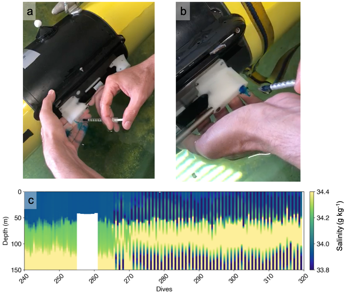
Fig. 6.1 a) A working pump CTD: There is a flow of the input dye. b) A pump CTD that failed: There is no flow of the blue dye. (Image credit: Nikolaos Zarokanellos). c) Example of uncorrectable thermal-inertia as a result of a blocked inflow (perhaps by a particle) which, after a few weeks regained flow (this data has been corrected for thermal-inertia already where possible). A pump failure may look like this too. (Isabelle Giddy)
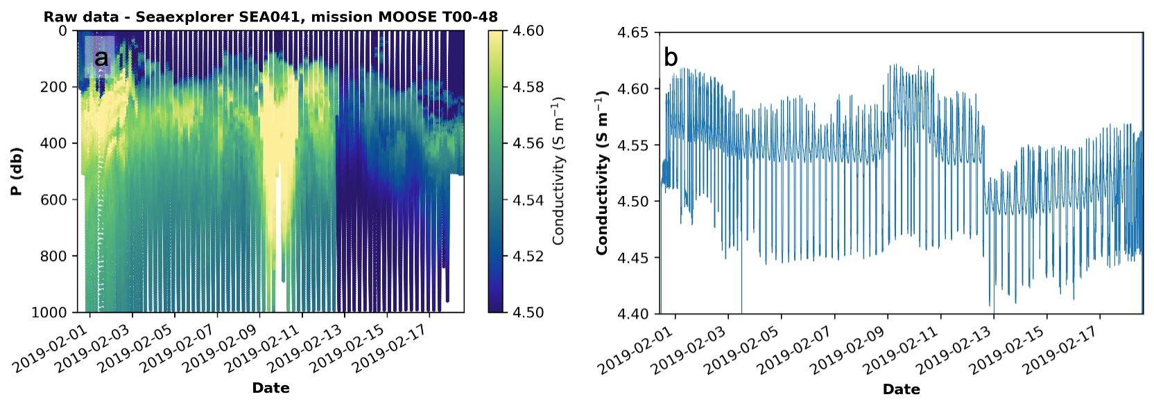
Fig. 6.2 a) Conductivity measured during a SeaExplorer mission in which the pumped CTD failed. The failure of the pumped CTD (on SeaExplorer) was possibly due to a particle in the pump system. b) Time series of conductivity shows that when the pump failed, there was a sudden drop in conductivity. It is hard to know if the slope observed afterward is natural due to the cleaning of the CTD cell, thus making correction by a constant offset questionable. A similar conductivity jump has also been observed on a Slocum glider equipped with an unpumped CT after a likely landing (abort same depth).
Regarding the biofouling of a particle, if the user observes drifting in the conductivity in the real-time data, especially on the stable deep waters, the glider pilot can try to increase the flow of the water that passes from the CTD to avoid this sensor shifting. To do that, the glider pilot needs to have a few steep dives (there is a limitation on how steep we can do). After a few dives, this procedure may result in the particles being flushed out, and then the steepness of the dive can be returned back to normal. If that does not work, the glider pilot needs to plan for a recovery.
A failed pump can sometimes be fixed by a simple reboot of the system. If particles block the inflow, because the inflow is narrow, it is not easily flushed. In most cases, thermal-inertia as a result of pump malfunction cannot be corrected for. A failed pump can be identified in realtime and the sensor switched off (refer to Fig. 6.1 above).