Sensors and integrations
Contents
3. Sensors and integrations
3.1. Oxygen sensors
3.1.1. Aanderaa Optodes
Aanderaa optodes are the most widely used oxygen sensor on ocean gliders and a large body of work has now been dedicated to their characterization (e.g. (Bittig et al., 2018)). These sensors are based on the oxygen luminescence quenching of a platinum porphyrin complex (fluorescent indicator) that is immobilized in a sensing foil. This offers low power consumption, good long-term stability, low fouling sensitivity while not being sensitive to H2S or freezing. Aanderaa optodes have seen several important developments since they were introduced in 2002, with various hardware and firmware revisions which we outline below (see also Fig. 3.1).
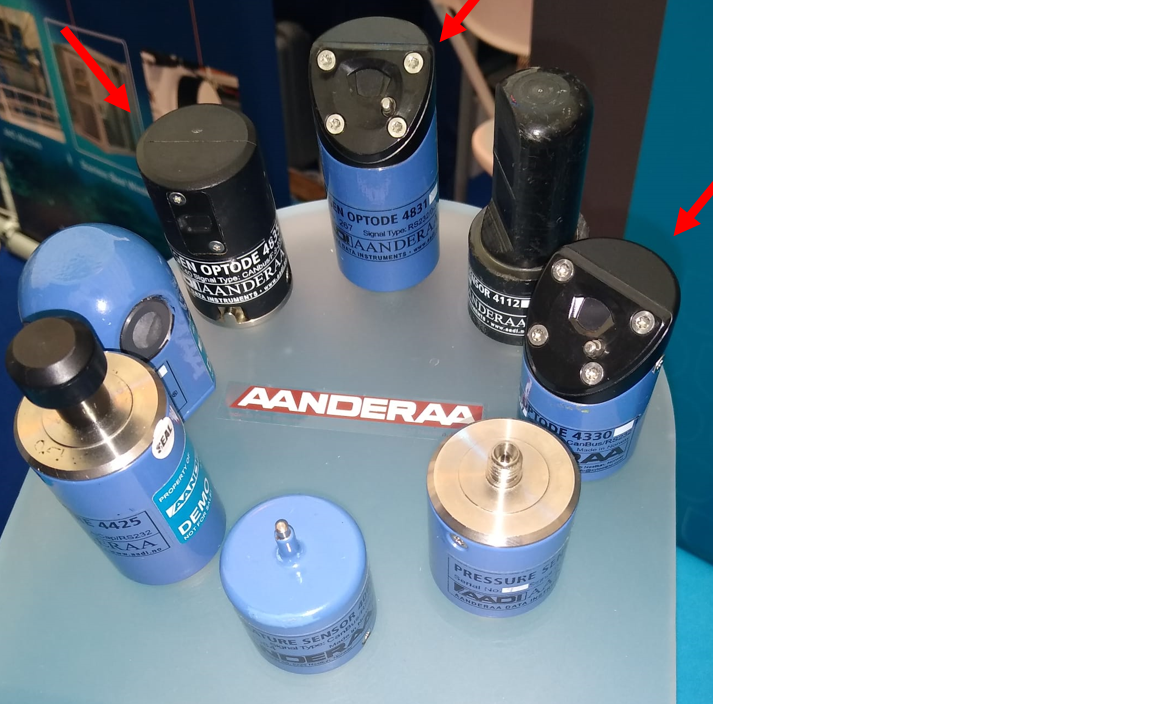
Fig. 3.1 Suit of Aanderaa smart sensors. Oxygen optodes are indicated by red arrows.
3.1.1.1. Hardware design: blue or black
While mostly cosmetic, the colour of the optode is a useful shorthand for the two main optode designs. The 3835 and 4835 optodes both feature a black housing with the temperature sensor integrated into the base of the sensor near the connector. This results in a large thermal mass and increases the response time of the temperature sensor significantly. The blue 4330 and 4831 sensors move the thermistor next to the sensing foil which results in much improved performance of the temperature sensor. With an increase in accuracy to 0.03 °C from 0.05 °C, and time-response reduction to <2 seconds rather than ~10 seconds (Data Instruments AS, 2018). All optodes other than the 4831 use a 10 pin Lemo connector, these connectors can’t be connected when wet and are prone to crevice corrosion. The 4831 is therefore recommended for all applications with it’s Subconn wet-pluggable connector. Older optode versions (3830) have a titanium housing in the same form factor as the 3835. Some early Slocum gliders include a 5013 optode which is identical to the 3830.
3.1.1.2. Foil type: F or standard
Most optodes use the PreSens PSt3 foil (PreSens - Precision Sensing GmbH), these have as standard a black opaque protective layer protecting the pink sensing layer. For glider applications the “F” type foils are typically preferred as these remove the opaque layer which results in much faster diffusion across the foil, and therefore faster sensor response (τ = 8 s compared to ~ 25 s (Bittig et al., 2014)). However, removal of the protective layer makes the foil more susceptible to UV radiation, and is known to reduce the sensor stability, especially when exposed to strong sunlight. Newer 4330F and 4831F optodes (Since July 8th 2018) use an improved formulation of the Presens fast foil which are less sunlight sensitive and have much lower noise levels. These can be identified by their white appearance. It is recommended that older F-type instruments (with the pink foils) are upgraded with these improved foils. Otherwise, foils should typically not be replaced unless mechanically damaged (light intrusion) as older foils perform better, with less drift than new ones.
3.1.1.3. Calibration equation and firmware versions
The way optode foils are initially calibrated by Aanderaa, and how the measured values are processed by the optode varies between different optode versions.
The optode illuminates the sensing foil with both a red and blue LED.
Since the red light does not produce fluorescence in the foil the phase measurements are obtained from the difference between the blue (P1) and the red (P2) excitation.
TCphase = A(T) + (P1 - P2) · B(T)
Where TCphase is the temperature compensated phase and T is the measured optode temperature.
A and B are temperature dependent coefficients which allow for temperature compensation of the phase measurement.
However, for most 4330, 4831 and 4835 optodes these are not used, such that A(T) = 0 and B(T) = 1.
This can be confirmed by communicating with an optode and inspecting the PTC0Coef and PTC1Coef properties.
Similarly, older optodes have their calibration (and recalibration) applied though the modification of the PhaseCoef coefficients.
On later optodes the calibration is not applied in phase space, but on the oxygen concentration though the use of the ConcCoef0 and ConcCoef1 coefficients (PhaseCoef0 and PhaseCoef1 are set to zero and 1 respectively).
Consult your optode calibration sheet and confirm which terms are being used.
For older 4xxx series optodes (4330 serial numbers < 1000) the temperature compensated phase is then used to calculate calphase (calibrated phase).
With newer optodes TCphase = calphase.
For the 3830, 3835 and 5730 series optodes the calibrated phase is known as DPhase.
There are three different calibration equations used to convert the phase (calphase or dphase) to oxygen:
The “Mk1” equation used by the older 3835 optodes uses a 5 x 4 matrix of coefficients.
The “Mk2” equation is used by non-multipoint calibrated 4330(F) and 4835 optodes, and uses a 2x14 matrix (FoilCoefA and FoilCoefB) together with a 2 x 27 matrix for the polynomial degree, this second matrix is the same across all of these type optodes.
Newer multipoint calibrated optodes use the Stern-Volmer (SVU) equation proposed by (Uchida et al., 2008) which has 6 terms.
The SVU equation was introduced with firmware version 4.4.8.
As of 2019 all new Aanderaa optodes are multipoint calibrated as standard.
Non-multipoint foil calibrations are based on a common characterization of a production batch.
Multipoint calibrations consist of 40 calibration points across a range of concentrations and temperatures and offer improved accuracy and should be preferred when purchasing these sensors.
Consult your optode foil calibration document to verify which version your optode is using.
Understanding these differences in how the calculations are performed is important when recalculating oxygen from the phase readings, such as when compensating for lag.
The resultant oxygen concentration (in μmol L-1) and saturation (%) need to be corrected for salinity. Optical oxygen sensors do not measure salinity, but they can be configured to apply this salinity correction internally. We recommend to never change this from the default value of zero and to always apply a correction based on matched salinity during RTQC or DMQC. Aanderaa currently use the “combined” fit from Garcia and Gordon (1992) for this correction in their documentation. However following Bittig et al. (2015), this should be ideally be done using the Benson and Krause Jr. (1980) data.
Regardless of the optode version, oxygen can be recalculated from the calibrated phase (calphase or dphase) using the approach of (Uchida et al., 2008).
During the initial months of storage/use a Foil maturation process occurs resulting in lower readings by several %.
On more than 1000 sensors, the maximum observed maturation induced drift has been 8 % for sensors with non-factory pre-matured WTW foils (model: 4835, 4531 and 5730 Steinsvik) and 6 % for sensors with factory pre-matured PSt3 foils (model: 4330, 4831, 5331 hadal).
During/between field deployments there are possibilities for end users to post-adjust the sensors either by a one-point air-saturation adjustment or by taking reference samples (e.g. water samples and Winkler titration) and/or using a well-calibrated sensor in parallel.
If done correctly such adjustment should result in an absolute accuracy of around 1 % for multipoint calibrated sensors (models: 4330, 4831, 5331 and 5730) and 3 % for two-point calibrated sensors (models: 4835 and 4531), see below for more information about factory calibrations.
The drift will decrease over time so during the second year it is not likely to be higher than 1-2 %.
After this time, it should be less than 0.5 % per year, unless the foil is mechanically damaged (Data Instruments AS, 2018).
3.1.2. RBR coda T.ODO
The RBRcoda T.ODO uses the same foils and methods as optodes 4831 and 4831F, so everything specified for the 4831 will also apply to this sensor. RBR refers to the standard optode (~30 s τ) foil as “slow” and the fast (~8 s) as “standard”. Newer sensor foil design (~1 s response) is called “fast”. The RBR sensor has a smaller form factor than the Aanderaa optodes, but is overall similar to a 4831 with the temperature sensor very closely located to the sensing foil. This sensor has recently been implemented in gliders, and little is known about their long-term performance.
3.1.3. JFE Advantech RINKO
AROD-FT sensor (RINKO JFE) is used for the SeaExplorer gliders (Alseamar) and for some Argo floats (small size and low power consumption) (see Fig. 3.2). These sensors use the same dynamic quenching principles as the other optical oxygen sensors (Aanderaa and RBRcoda) but made from different materials. The luminophore is coated onto the optical window rather than being embedded in a foil. They have a much faster response time (less than 1 s to 63 %) compared to foil based optical oxygen sensors while maintaining good accuracy (±2 μmol kg-1). These sensors are individually multipoint calibrated by the manufacturer (16 points with 4 temperatures and 4 DO concentrations). The DO reference standards used for these calibrations are produced by saturating the primary mixtures with DO concentrations of approximately 4 %, 10 %, 17 % and 25 % respectively (certified by the National Metrology Institute of Japan).
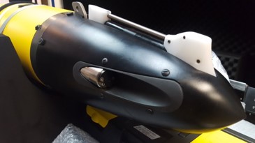
Fig. 3.2 AROD-FT sensor mounted on a SeaExplorer glider (credit: ALSEAMAR)
The DO concentration is calculated from the (Uchida H. and McTaggart, 2010) equation with 9 calibration coefficients. A second equation is used to take into account the pressure effect (a linear equation with one calibration coefficient). Finally, the salinity-compensated DO concentration is calculated by multiplying the factor of the effect of salt on the oxygen solubility (Benson and Krause Jr., 1980) and (Garcia and Gordon, 1992). This is similar to procedures used on other optodes.
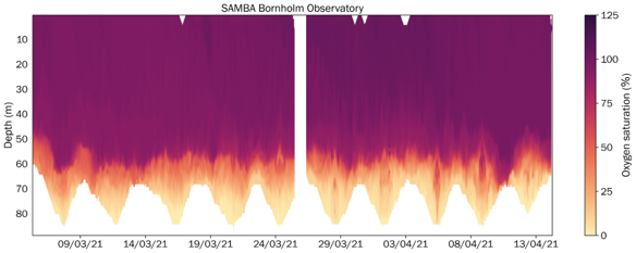
Fig. 3.3 Oxygen saturation from a Rinko AROD-FT on a SeaExplorer glider in the Bornholm Basin (credit: Voice of the Ocean Foundation and University of Gothenburg). Note that this sensor was a recent acquisition and had little opportunity to drift in storage.
Recent deployments of a SeaExplorer glider equipped with an AROD-FT sensor have shown long-term stability (low drift over time) but with a significant offset observed during sections in the Ligurian Sea (on average 10-15 \(\mu\)mol/kg). Deployments in the Bornholm Basin have shown good agreement across a wide range of oxygen concentrations with a nearby BOOS monitoring station (see Fig. 3.3.)
3.1.4. Clark electrode polarographic sensor (SBE 43, SBE 43F and SBE 63)
The SBE 43, SBE 43F and SBE 63 are individually calibrated with a calibration drift rates of less than 0.5% over 1000 h of operation. These sensors have been used in Seagliders and Spray and also in moorings and Argo floats. Sensors are designed for use in a CTD’s pumped flow path, providing optimal correlation with CTD measurements. Elapsed time between the CTD and associated oxygen measurement is easily quantified, and corrected for, in post-processing. The black plenum and plumbing’s black tubing blocks light, reducing in-situ algal growth. Response time τ varies from 2-20 sec depending on the membrane thinness, ambient water temperature and flow rate. Drift thresholds for sensor performance should be established prior to data collection, to determine how often instruments should be serviced, validated, and returned to Sea-Bird for a full service and calibration. It is recommended to do validation in the lab before and after deployment/recovery and while the sensor is in the water (if possible). For this task, Winkler samples or a clean, calibrated reference sensor will be required. (Information from https://www.seabird.com) Before storing the SBE 43 sensor, it is recommended to disconnected it from the CTD if connected to it, rinse it with a syringe (avoiding high pressure of water because we can damage the membrane) and add a sponge with some sodium sulphite in order to remove all oxygen on the membrane. Some researchers are not recommending using this sensor in gliders. SBE 43 is very reliable in CTD profiling systems and moorings, but it is very sensitive and not robust enough for glider work. For example, when working in low temperature regions, you have to keep the sensor protected to avoid icing, a solution is to use an insulated cover with some handwarmers inside, but this is quite complicated when being in a boat a -10 degrees for a couple of hours. Sometimes it is impossible to do a post-deployment calibration because the membrane is broken.
3.2. Sensor integration with gliders
3.2.1. Mounting location
3.2.1.1. Spray
input from expert needed
3.2.1.2. Seaglider
On Seagliders the oxygen sensor is normally mounted externally behind the CT sensor (see Fig. 3.4). Given this exposed location it is important to mount the optode with the sensing foil facing away from incident light to avoid unnecessary UV exposure.
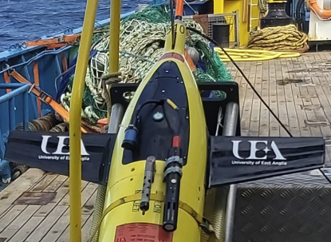
Fig. 3.4 UEA OGIVE seaglider with 4330F optode, together with NOC LoC spectrophotometric pH, unpumped SBE CT and Fluidion potentiometric pH sensor.
3.2.1.3. Slocum
On slocum gliders the oxygen optode is typically installed aft close to the fin (Fig. 3.5).
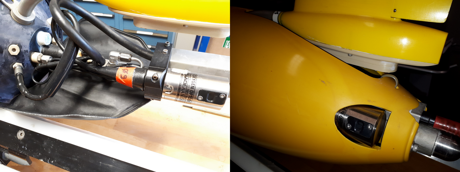
Fig. 3.5 Standard Aanderaa optode 3830 mounting under the fin of the Slocum G2.
However, this positioning is not ideal for oxygen measurements due to the optode being within a region of laminar flow (Moat et al., 2016), additionally the optode response time has been observed to be dependent on the sensor orientation relative to the direction of flow (Bittig et al., 2014).
An alternative mounting of the Aanderaa optode in a more prominent location fore of the glider fin has been demonstrated as being much more suitable for measuring oxygen on gliders (Fig. 3.6) (Nicholson and Feen, 2017). This mounting location means that the sensor foil faces the flow directly and therefore the diffusive boundary layer thickness at the optode membrane is minimized, reducing the optode response time. Furthermore, this mounting location also means that in-situ in-air calibrations can be performed during deployment (similar to those done with Argo floats) which are beneficial when processing the DM oxygen data (see ‘in-air calibration’ section).
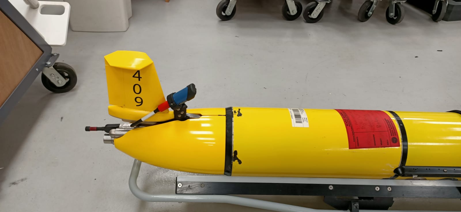
Fig. 3.6 Slocum glider showing alternative mounting of an Aanderaa optode perpendicular to the fin.
3.2.1.4. SeaExplorer
On SeaExplorer gliders, all existing oxygen sensors are installed in the front wet payload section (called the nose cone). External mounting is also feasible using external puck mounts on the dry payload which located approximately 1/3 of the way back, but this configuration is rare and generally only used during instrument trials. The Rinko AROD-FT is generally installed on the forward starboard connector, with the sensing foil and temperature probe 15 centimetres back from the tip of the nose and lightly sheltered to avoid damage when making contact with the nose. Both the foil and temperature probe are well exposed to flow. The new RBR Coda integration is also planned to present the foil and probe slightly set back from the tip of the nose, while remaining exposed to unmodified flow. The SBE43 is found only when accompanied by a Seabird pumped CT sensor; both of these sensors are placed in the nose where the RBR Legato CT sensor can be seen in Fig. 3.7.
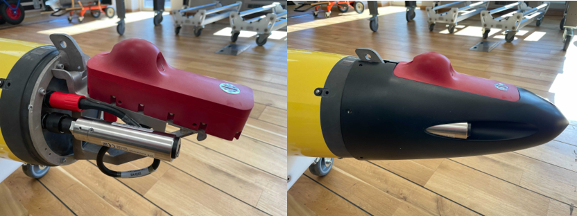
Fig. 3.7 Rinko AROD-FT in the flooded nose cone payload bay of a SeaExplorer next to an RBR Legato sensor.