Sensors and integrations
Contents
3. Sensors and integrations
3.1. Chlorophyll a sensors
All existing sensors function using the same principle, i.e measuring the fluorescence emission of chlorophyll a directly after it has been excited. The sensor generally emits light at determined wavelengths chosen based on the target variable (Chlorophyll a, phycocyanin, CDOM etc.). Specific filters are chosen, again based on the target variable, and placed in front of a detector which will measure the fluorescence intensity. The emitted light is generally lower in energy (larger wavelength) than the previously absorbed light (shorter wavelength). The various sensors available on the market and implemented on gliders can have slightly different combination of excitation/emission wavelengths. We summarized below the different EX/EM combinations:
Sensor |
Excitation/Emission |
|---|---|
RBR Tridente |
470nm/695nm or 435nm/700nm |
WetLabs ECOPuck (FLBBCD, FLBBPC, FLNTU, FLBBPE) |
470/695 nm |
Seabird SeaOWL |
470/690 nm |
TriOS Nanoflu |
470/682 nm |
All sensors apart from Nanoflu (not sure about RBR tridente, I think it does internal ‘computation’ and gives scaled values and no raw data??). The WetLabs ECOPuck and the SeaOWL, estimate fluorescence by subtracting a dark count (DC) to the raw counts (engineering units) and multiplying all by a scaling factor (SF). This calibration factors (DC and SF) are normally provided by the manufacturer. (Mention that values can be invalid for a variety of reasons and recommend recalibration etc. or maybe it should go in another section??)
3.1.1. RBR Tridente
The RBRtridente three channels optical sensor, capable of making multiple fluorescence and backscatter measurements simultaneously. The default set up measures chlorophyll, backscatter and FDOM. Filters can be placed on both the LED and the detector upon request thus allowing for measurements of a customized variables.
The calibrated range for the chlorophyll a channel is 1 0-50μg/L and the detection limit is 0.01μg/L. The temperature range is -5°C to +35°C. This sensor gives the possibility for a very high sampling rate up to 32 Hz and has a rather low power consumption, 20mJ/sample (4Hz or slower) and 384mW (8Hz or faster). The sensor exists in both version for a dry bay or a wet section. The windows are specifically made of fused silica which allows for the transmission of ultraviolet radiation. RBR design avoided the use of epoxy or resins to avoid issues related to autofluorescence. Furthermore, in order to address issues related to drift in power of the LED and variations in power output based on temperature, a reference photodiode to monitor the LED has been implemented. As the photodiode itself is temperature sensitive, there is a second thermistor to track the photodiode and apply a proper compensation.
Shall we explain the whole process that happens internally for every sample? reference signal, how the corrected signal is computed etc.?
3.1.2. WetLabs ECOPuck
Add specific info
3.1.3. Seabird SeaOWL
Add specific info
3.1.4. TriOS Nanoflu
Add specific info
3.2. Sensor integration with gliders
3.2.1. Mounting location
3.2.1.1. Spray
input from expert needed
3.2.1.2. Seaglider
input from expert needed
3.2.1.3. Slocum
input from expert needed
3.2.1.4. SeaExplorer
On SeaExplorer gliders, the various existing fluorescence sensors can be installed in either/both (depending on the sensor) the front wet payload section (called the nose cone) or the dry payload section in one of the four (4) puck ports. External mounting using the external puck mounts on the dry payload section is also feasible, but this configuration is rare. (we can add more details and photos too) The mounting options available for the different sensors on a SeaExplorer can be seen in Fig. 3.1.
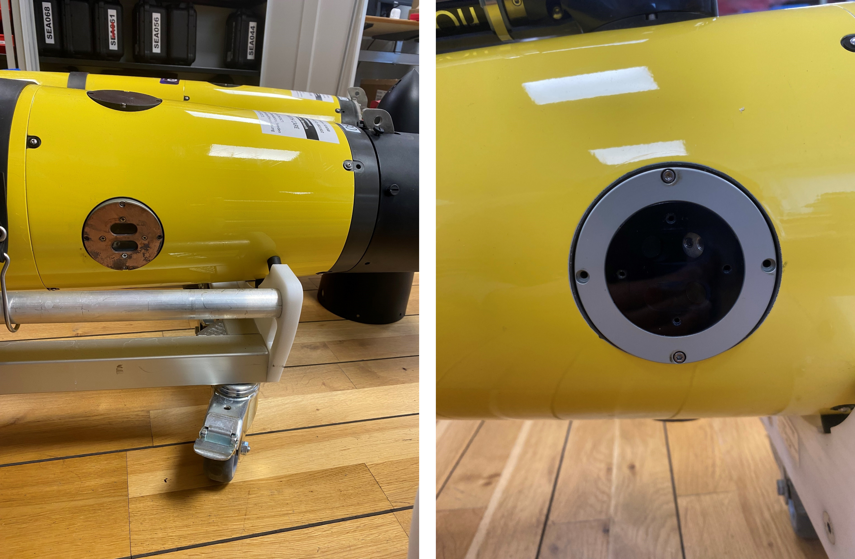
Fig. 3.1 Wetlabs ECOPuck mounted on one of the side ports in the dry payload section of a SeaExplorer. In the left photo, the protective copper plate used to prevent biofouling is present while it was removed in the right photo.